LLM-Aided HLS Dataflow Optimization: a SHA-256 Case Study
Apr 06, 2026

Overview
Since the rise of LLMs, the academic community has rapidly explored LLM-for-HLS. HLSPilot1 combines pattern-guided C-to-HLS transformations with design-space exploration driven by real compiler reports, demonstrating that LLMs can go beyond code generation to pragma tuning under tool feedback. HLS Eval2 complements this by providing a benchmark suite with automated C-simulation and synthesis validation, making LLM-for-HLS progress measurable. Together, these efforts point to three areas of strong potential: lowering the entry barrier for HLS users, accelerating kernel-level optimization, and scaling design-space exploration with synthesis-in-the-loop. Following these trends, an annual FPGA design competition piloted an LLM-aided Vitis HLS optimization track. The track was jointly initiated by the AMD University Program to bridge the gap between academic research findings, student design competitions, and industry engineering practice.
This blog analyzes one submission from the students which used LLMs to optimize the SHA 256 kernel on an UltraScale+ device using Vitis HLS 2025.2, achieving a 2.22× speedup and 52% latency reduction in two weeks. In practice, the students primarily used gpt-5-turbo and claude-sonnet-4 as interactive design advisors. Through this case study, we validate the effectiveness of general-purpose LLMs in accelerating HLS kernel performance optimization and propose a repeatable four-phase workflow that clearly delineates human and LLM responsibilities at each stage. We also present a set of prompting strategies that proved critical for eliciting high-quality, synthesizable suggestions from the LLM.
Image Zoom
The Baseline Kernel Architecture
HMAC-SHA-256 (FIPS 198-1) produces a 256-bit authentication tag by calling SHA-256 twice with key-dependent pads. Nearly all of the computational cost lives in the SHA-256 compression engine, which processes 512-bit message blocks in three stages: preprocessing (padding), message-schedule generation (expanding 16 words into 64), and a 64-round digest loop. HMAC wraps this engine with lightweight key-XOR and stream-routing logic. The detailed algorithm, including the key equations, is provided in the Appendix.
In the baseline, sha256_top wires these stages with hls::stream FIFOs under #pragma HLS DATAFLOW. Although DATAFLOW suggests overlap, the dependencies are block-granular: schedule generation is driven by a full 512-bit block, and the digest consumes the Wt stream across a block. In practice, this pushes the stages toward near-serial execution and motivates the architecture changes described later.
Every optimization begins with understanding the current design. The starting point here is the HMAC-SHA-256 kernel, targeting the xcu200-fsgd2104-2-e part with Vitis HLS 2025.2. The baseline achieves 880 cycles at a Vivado post-synthesis clock period of 4.027 ns, yielding an execution time of approximately 3.54 µs. The core of SHA-256 is a 64-round compression function operating on 512-bit message blocks. The following diagram shows the original three-stage dataflow architecture and the data dependencies between stages:
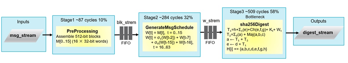
Total co-simulation latency: 880 cycles. Sequential dependency: stages cannot overlap and the Stage 3 (sha256Digest) dominates at 58% of total latency.
PreProcessing and generateMsgSchedule are connected by a FIFO but have a strict full-block dependency; the FIFO adds overhead without enabling overlap. The digest stage dominates at 58% of total latency. Cycle counts are approximate and derived from HLS co-simulation (880 cycles total).
The design consumes 8,119 LUTs (0.69% of 1,182,240 available) and 13,704 FFs (0.58% of 2,364,480 available). Before engaging the LLM, the engineer ran HLS synthesis once and collected the report.
The first interaction was deliberately open-ended. The engineer provided the full source code and synthesis report, then asked:
“You are a senior Vitis HLS engineer and FPGA hardware architect. Analyze this code and tell me the optimization directions and their feasibility.”
The LLM returned a structured analysis identifying that two of the three dataflow stages had a strict sequential dependency: the FIFO between them added overhead without enabling any overlap. It also flagged the digest stage as the dominant bottleneck at 58% of total latency. The key insight here is not about SHA-256. It is that an LLM, given a synthesis report and source code together, can perform bottleneck identification that would otherwise require an experienced engineer reading through timing and latency breakdowns manually.
LLM-Aided HLS Optimization Workflow
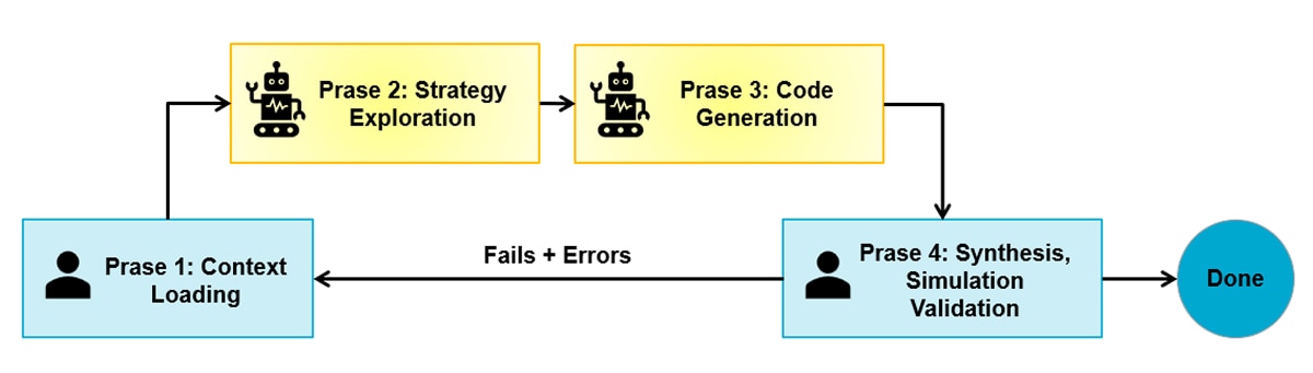
Through this experiment, a natural collaboration pattern emerged that generalizes well beyond this particular design. The workflow has four phases, repeated iteratively.
- Phase one: context loading. Provide the LLM with the current source code, the HLS synthesis report, and the target device constraints. Include latency breakdown, initiation intervals, and resource utilization. The richer the context, the more targeted the suggestions. A common mistake is asking for optimization advice without providing the synthesis numbers. Without them, the LLM falls back on generic recommendations rather than addressing the actual bottleneck.
- Phase two: strategy exploration. Ask the LLM to propose multiple strategies with trade-offs. A prompt that worked well in practice:
“Given this synthesis report and device constraints, propose several optimization strategies. For each, explain the expected latency benefit, the resource cost, and any risks.”
In this experiment, the LLM proposed five strategies for the second optimization round. The suggestions ranged from full combinational unrolling, which offers maximum performance but is unrealistic for timing closure, to two-way block parallelism, which delivers a solid gain at acceptable resource cost. The engineer selected two-way parallelism after checking that LUT utilization would remain well within the U200’s abundant budget. Having multiple options with explicit trade-offs is far more useful than a single recommendation.
- Phase three: targeted code generation. Once a strategy is selected, ask the LLM to generate the specific code changes. The most effective prompts were narrow and explicit about constraints:
“Merge generateMsgSchedule and PreProcessing into a single function to improve parallelism. Generate the merged function and the updated top-level function. Do not modify other function calls. Be careful about dataflow conflicts and illegal connections.”
Notice the structure: the prompt names a concrete action, states the performance objective, draws an explicit boundary around what must not change, and flags a known tool pitfall up front. This level of specificity consistently produced higher-quality generated code than open-ended requests such as “make it faster.”
- Phase four: synthesize, simulation, validate, and feed back. The human runs HLS synthesis and co-simulation on the generated code. If errors occur, the error messages become the next prompt:
“Synthesis reports errors [XFORM 203-313] and [RTGEN 206-102]. Fix the conflicts.”
The LLM then diagnoses the error. In this case, it identified a pragma conflict between PIPELINE and DATAFLOW at the same hierarchy level, as well as an unconsumed stream left over from the original architecture. The fix is generated, the human re-synthesizes, and the loop continues.
This loop has four phases: context loading, exploration, code generation, and validation. It typically converges in two to three iterations per optimization step.
Evaluating LLM-generated Optimization Advice
Across three major optimization iterations in this experiment, a consistent pattern of LLM strengths and weaknesses emerged.
The LLM excelled at architectural pattern recognition. Given a dataflow graph with sequential stages connected by FIFOs, it identified the anti-pattern: DATAFLOW directives applied to stages that cannot overlap. It recognized that the SHA-256 message schedule recurrence depth is 16, not 64, and proposed a circular buffer, a well-known technique that nonetheless requires understanding the algorithm to apply correctly.
The LLM was effective at design-space exploration. When asked for optimization strategies, it generated a ranked list with quantitative reasoning about each option’s feasibility on the target device. This is perhaps the highest-value use case: compressing hours of documentation reading and mental modeling into a single interaction.
The LLM produced synthesizable code at roughly 80% first-attempt correctness. The generated code was structurally sound, with correct stream interfaces, proper loop labels, and appropriate pragma placement. The remaining 20% required human correction.
The LLM consistently failed at three things. First, pragma interaction rules: it applied a #pragma HLS PIPELINE inside a function that was already governed by a #pragma HLS DATAFLOW region, violating the constraint that these two directives cannot coexist at the same hierarchy level. This rule is documented in the Vitis HLS user guide but is apparently not well-represented in LLM training data. Second, dead code from refactoring: after merging two functions, it preserved a stream duplication utility that no longer had two consumers, causing an illegal connection error. Third, boundary conditions in algorithmic logic: the message padding paths required careful human verification through test vectors.
These gaps are not inherent to LLMs; they reflect missing domain context. Structured prompting already narrows the failure rate, and the remaining issues could be further mitigated by pairing the LLM with domain-specific agents or retrieval-augmented skills backed by an HLS knowledge base covering pragma constraints, common refactoring pitfalls, and tool-specific error patterns.
The Human-LLM Optimized Architecture
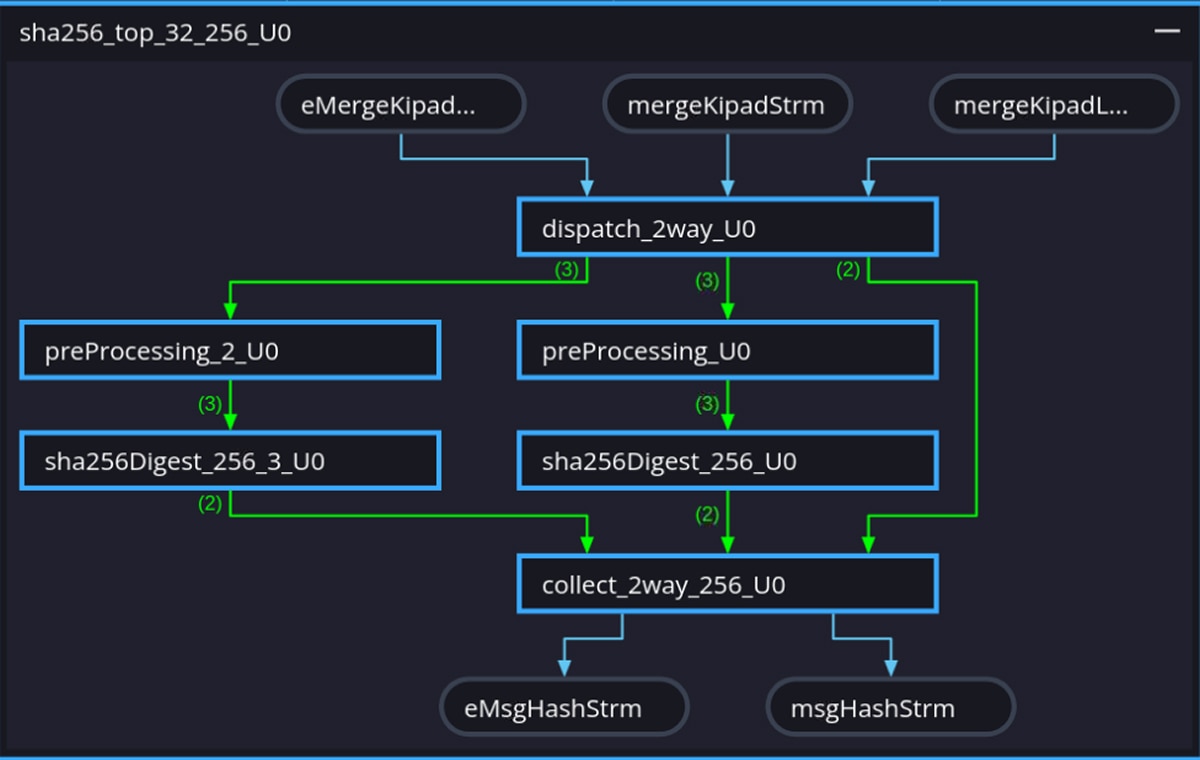
The four-phase workflow converged on two complementary transformations. First, function merging: the original PreProcessing and generateMsgSchedule stages were combined into a single function, eliminating the inter-stage FIFO overhead and reducing the path from three sequential stages to two. Second, two-way block parallelism: a dispatch/collect wrapper distributes message blocks round-robin across two identical processing paths, each containing the merged preprocessing stage and its own sha256Digest instance. The following diagram shows the resulting architecture:
Image Zoom
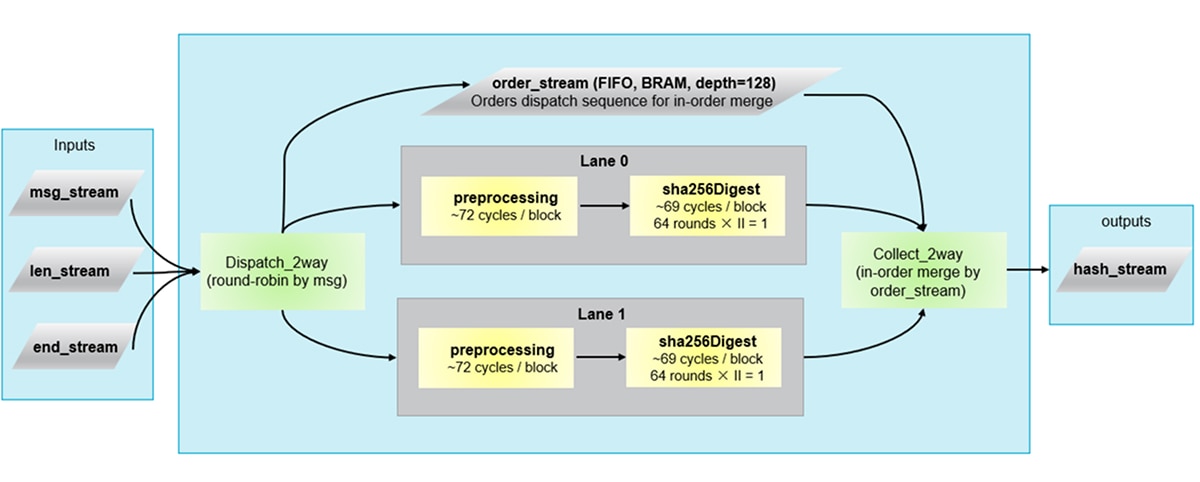
Each path contains a merged preprocessing stage that performs padding and W-schedule generation in one function and runs in 72 cycles per block. That stage feeds directly into a sha256Digest instance that runs the 64-round compression with II=1 and completes in 69 cycles per block. The dispatch_2way module distributes blocks round-robin, and collect_2way merges results in order. Both sha256Digest instances share the same 4.446 ns estimated clock, set by the merged preprocessing critical path. This is well within the 5.00 ns target clock period.
Function merging collapses the original three-stage pipeline into two stages per path, and two-way parallelism further halves the effective block processing time. After accounting for dispatch, collect, and the surrounding HMAC wrapper overhead, the net result is a 2.22× speedup at the full HMAC level.
Results Summary
|
Baseline |
After optimization |
Latency (cycles, cosim) |
880 |
426 |
Vivado clock period (ns) |
4.027 |
3.739 |
Execution time (µs) |
3.54 |
1.59 |
LUT (Vivado) |
8,119 (0.69%) |
19,256 (1.63%) |
FF (Vivado) |
13,704 (0.58%) |
22,917 (0.97%) |
BRAM (Vivado) |
1 (0.02%) |
15 (0.35%) |
Correctness is verified at each stage via C/RTL co-simulation against FIPS 180-4 test vectors and Vivado implementation using Vitis HLS 2025.2. Resource utilization remains well under 2% of the U200, confirming that the speedup comes from architectural restructuring rather than brute-force resource expansion. The entire optimization process took approximately two weeks, with an estimated 60% of the intellectual contribution coming from LLM interactions and 40% from human synthesis validation, debugging, and decision-making.
The Vitis HLS Dataflow Viewer provides visual confirmation that the intended pipeline architecture was correctly inferred by the tool. Fig. 3 and Fig. 4 show the viewer output for the baseline and optimized designs respectively. Because DATAFLOW is a dynamic optimization whose behavior is fully determined only after RTL co-simulation, the viewer plays a practical role in the optimization loop: it lets engineers inspect the inferred channel structure, verify FIFO depths, and catch structural mismatches early before committing to a full implementation run.
Image Zoom
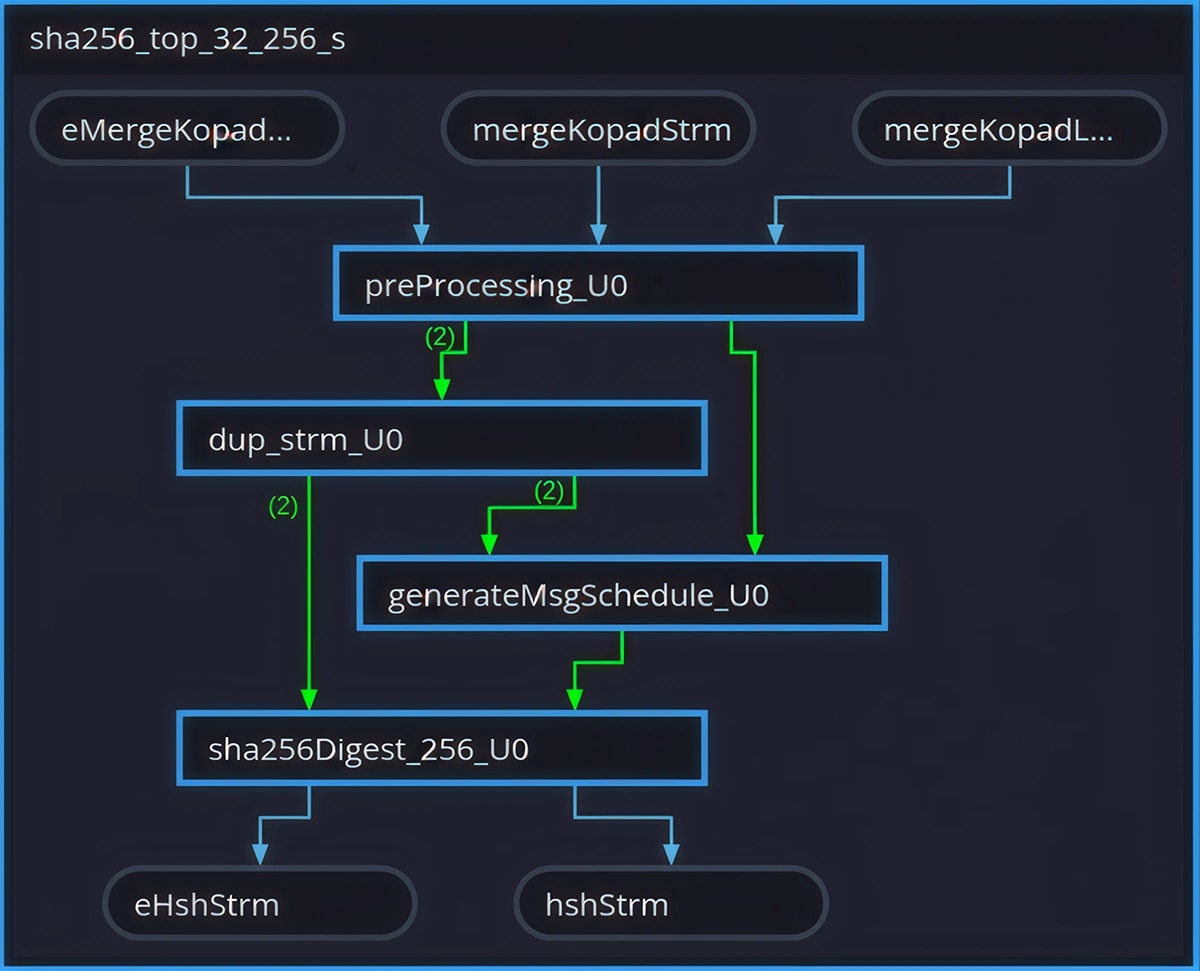
Image Zoom
Effective Prompting Strategies for HLS Optimization
Based on this case study, several prompting practices proved consistently effective.
- Use role priming to set the right abstraction level. The prompt “You are a senior FPGA hardware architect” consistently produced responses focused on architectural trade-offs rather than superficial code-level changes.
- Always provide the synthesis report alongside the code. The LLM’s analysis quality improves dramatically when it can see actual latency numbers, initiation intervals, and resource percentages rather than reasoning about the code in isolation.
- Ask for multiple strategies, then select. The human’s role is strongest in the selection phase, evaluating feasibility against device constraints, schedule pressure, and risk tolerance. The LLM’s role is strongest in the generation phase, producing a broad menu of options quickly.
- Be explicit about what must not change. Prompts like “do not modify other function calls” and “keep the top-level interface unchanged” prevented the LLM from generating solutions that were locally optimal but broke system integration.
- Name the specific tool errors when debugging. Providing exact error codes (e.g.,
[RTGEN 206-102]) allowed the LLM to diagnose root causes accurately. Vague descriptions like “synthesis failed” produced vague suggestions.
Conclusion
The four-phase workflow described here is not specific to SHA-256. It is a general, repeatable approach for HLS kernels where the engineer can ground decisions in real synthesis and co-simulation feedback. In this loop, the LLM is most valuable as a high-bandwidth accelerator for architectural reasoning and refactoring draft work, while the human owns closure: constraint management, tool-driven validation, and end-to-end correctness.
Looking ahead, hardware design still requires rigorous physical validation, so LLMs augment architectural exploration rather than replace sign-off. Even at this early stage, they have already lowered the expertise threshold and compressed the optimization cycle enough for entry-level engineers to reach results that previously demanded deep FPGA experience. As the Vitis tool chain moves toward deeper AI-agent integration, structured prompting combined with domain-specific agents or skills backed by an HLS knowledge base can guide LLMs toward more reliable and context-aware suggestions, progressively narrowing and in some cases closing the gaps identified.
References
[1] S. Abi-Karam and C. Hao, “HLS-Eval: A Benchmark and Framework for Evaluating LLMs on High-Level Synthesis Design Tasks,” 2025.
[2] C. Xiong, C. Liu, H. Li, and X. Li, “HLSPilot: LLM-based High-Level Synthesis,” 2024.
Additional Resources
Vitis High-Level Synthesis User Guide : https://docs.amd.com/r/en-US/ug1399-vitis-hls
Appendix: HMAC-SHA-256 Algorithm Detail
HMAC-SHA-256 (FIPS 198-1) produces a 256-bit authentication tag by running SHA-256 twice with key-dependent pads. In hardware, almost all of the cost sits in the SHA-256 compression engine; the surrounding HMAC logic (key pad, outer re-hash, stream routing) is comparatively lightweight.
SHA-256 processes the message in 512-bit blocks (16 words). Per block, the design decomposes into three stages:
- PreProcessing. Assemble bytes into 512-bit blocks and apply FIPS 180-4 padding (a single 1 bit, zeros, then 64-bit length).
- Message schedule generation (generateMsgSchedule). Expand each block into 64 words . The first 16 come from the block; the rest follow:
Wt = σ1 (Wt-2) + Wt-7 + σ0 (Wt-15) + Wt-16, t = 16…63
This recurrence is friendly to a 16-word circular buffer, a key detail for an efficient schedule generator.
- Digest rounds (
sha256Digest). Initializea…hfrom the hash state, then run 64 rounds:
T1 = h + Σ1 (e) + Ch (e,f,g) + Kt + Wt
T2 = Σ0 (a) + Maj (a,b,c)
a ← T1+T2, e ← d+T1
Here Σ0, Σ1, are fixed rotates, Ch and Maj are bitwise boolean functions, and Kt is a 64-entry constant table. After 64 rounds, the working variables feed forward into the hash state.
HMAC-SHA-256 calls SHA-256 twice. The first call hashes the message together with a key-derived inner padding. The second call takes the output of the first hash and hashes it again with a key-derived outer padding, producing the final 256-bit authentication tag. In the HLS implementation, both calls reuse the same compression dataflow; the only additional logic is key XOR and stream routing, which are lightweight by comparison.
Disclaimers
Third-party content is licensed to you directly by the third party that owns the content and is not licensed to you by AMD. ALL LINKED THIRD-PARTY CONTENT IS PROVIDED “AS IS” WITHOUT A WARRANTY OF ANY KIND. USE OF SUCH THIRD-PARTY CONTENT IS DONE AT YOUR SOLE DISCRETION AND UNDER NO CIRCUMSTANCES WILL AMD BE LIABLE TO YOU FOR ANY THIRD-PARTY CONTENT. YOU ASSUME ALL RISK AND ARE SOLELY RESPONSIBLE FOR ANY


Related Blogs
-
From Vector Search to Agentic RAG: Building an Enterprise Research Analyst with hipVS — ROCm Blogs
Learn how to build an agentic RAG research assistant using hipVS GPU-accelerated vector search on AMD Instinct GPUs, with multi-query decomposition, parallel retrieval, and cited sources synthesis.
July 14, 2026
-
When a Faster Kernel Doesn’t Speed Up Serving: Profiling FP8 KV Cache on AMD Instinct MI308X — ROCm Blogs
Learn how a 34% faster FP8 KV cache kernel delivered 0% E2E speedup, and how profiling attribution exposed the hidden dtype-cast cost on MI308X.
July 14, 2026
-
What to Expect at AMD Advancing AI 2026
Get a preview of AMD Advancing AI 2026, including key themes, sessions, and innovations shaping the future of AI. Discover how industry leaders are coming together to explore real-world use cases and strategies for scaling AI across the enterprise.
July 14, 2026
-
Local Image and Video Generation on AMD Ryzen™ AI Max+ Processor (Windows) — ROCm Blogs
Run ComfyUI natively on Windows on AMD Ryzen AI Max+ with ROCm 7.2.1—SDXL, Flux, and video workflows on the Radeon 8060S, no WSL.
July 13, 2026
-
Announcing the ROCm Certification Program
Build AI and HPC expertise on AMD Instinctt™ GPUs. Earn the ROCmt™ Certification with hands-on, production-ready skills.
July 13, 2026
-
GEAK Agent-Driven Optimization of the DeepSeekV4 MLA Kernel — ROCm Blogs
GEAK Agent accelerates DeepSeekV4 MLA kernel optimization with Triton and delivers SGLang E2E gains on AMD GPUs.
July 12, 2026
-
ZenDNN 6.0 FP16 Inference and MoE Acceleration
ZenDNN 6.0 takes the next step: FP16 functional support for AMD’s 6th Gen EPYC™ processors, MoE model optimization, and the vLLM compatibility window.
July 10, 2026
-
Fast Image Generation and Editing with SGLang Diffusion on AMD GPUs — ROCm Blogs
Serve and benchmark diffusion models for image generation and editing on AMD Instinct GPUs using SGLang Diffusion on ROCm.
July 09, 2026